Hence, in this post, we are going to explain about one of the basic things on how the computer would operate. It is DIGITAL LOGIC.
So, basically, what is Digital Logic?
The theory is " Logic gates (or simply gates) are the fundamental building blocks of digital circuitry. As their name implies, they function by “opening” or “closing” to admit or reject the flow of digital information by using digital electronics, which are ; Gates, Decoders, Multiplexers."
But to make you understand better, ill explain these, a bit more detailed.
Digital logic is the basis for digital computing.It is basic the basic to understanding how circuit and hardware are connected to computer. The signals of digital logic is represented by using numbers which are zeros and ones (0s and 1s).
There are four type of gates; AND, OR, NAND, or NOT gate. These gates are to process signals which represent true or false by using Truth Table. Another ways to process the signal is by using the Boolean Algebra.
AND gate
OR gate
NOT gate
NAND gate
NOR gate
TRUTH TABLE
Truth Table provide a method of accessing the validity or invalidity of performing any of the tasks to user requested. Each gates have two or more inputs excepts for NOT because it has only one input. Usually, the inputs are represented by using the letters A, B , and C. While the output is represented by using of any other letters. A Truth Table is the exact way to show the function of the logic gates. It shows the input and the output states for every possible combination. The symbol 0 represents FALSE and 1 represent TRUE.

BOOLEAN
Boolean Algebra or Boolean Logic resembles the ON and OFF circuit which all the signals are classified as either
Law:
Identity law: A + 0 = A and A & 1 = A.
Zero and One laws: A + 1 = 1 and A & 0 = 0.Inverse laws: A + A’ = 1 and A & A’ = 1.Commutative laws: A + B = B + A and A & B = B & A.Associative laws: A + (B + C) = (A + B) + C and A & (B & C) = (A & B) & C.Distributive laws: A & (B + C) = (A & B) + (A & C)andA + (B & C) = (A + B) & (A + C).
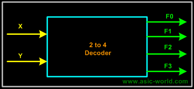
DECODER
A decoder is a circuit that converts code to signals (0s or 1s). For example, a decoder can convert the n-bit input into a binary signal. There are types of decoder, but most of decoders give only one n-input and 2,4,6, ... outputs.
This is the example :
So, are you clear now? But wait up, we're not done yet. So lets continue to the last digital electronic which is ;
MULTIPLEXER
A multiplexer (MUX) is a device that select several analog or digital input signals and translate the inputs that has been determined as the output into a single line. So basically, an MUX consusts of 3 parts;
1. A decoder that generates n-signals, which each of it indicates a different input value.
2. An array of AND gates, which each ot it combines one of the inputs with a signal from the decoder.
3. A single LARGE OR gate that incorporates the outputs, of the AND gates.

Anddd, we are done! I hope that you have already understood what"Digital Logic" actually is. For more info about the architecture and organization of computer, stay tuned! We have lots to share! Toodles!
Nur Ezany bt Elias
B031210213
BITM S1G2
No comments:
Post a Comment