Hello
guys. We meet again, now discussing over the most important topic in Computer
Organization and Architecture subject. It is no other but the MIPS. MIPS are the abbreviation
of Microprocessor without Interlocked Pipeline Stages. Internally, it is a
reduced instruction set computer (RISC) instruction set architecture (ISA)
developed by MIPS Technologies.
There are
some basic implementations of MIPS instruction sets to be fully acknowledged.
1.
Memory reference : lw, sw
2.
Arithmetic / logical : add, sub, and, or, slt
3. Control
transfer : beq,
j
The instructions are executed for PC
involving instruction memory and fetch instruction and for register numbers
including register file and reading registers. The execution always depends on
the instruction class itself. To calculate arithmetic result, memory address
for load or store and branch target address, the ALU must be used. Then, after
calculated the data memory will then be accessed for load or store.
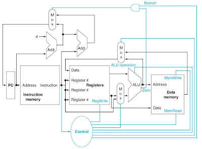
Here I
provide you an overview of a CPU:
Next is
the figure of the multiplexers:
The data lines in the circuit cannot be
wired together, as logic elements must be added. Those elements can be chosen
from the multiple sources and steers one of those sources to its destination. The
selection task is done by using multiplexor or can be called a data selector. Next
figure is the basic implementation of the MIPS subset with multiplexers and
control lines. There are three multiplexers altogether in the figure.
Now I’m going to give short explanations
about the multiplexers’ functions
embedded in the circuit.
1.
1st multiplexer (Mux) – controls what
value replaces the PC
2.
Middle Mux – steer the output of ALU or the
output of the data memory for writing into the register file.
3.
Bottom Mux – determine whether the 2nd
ALU input is from the registers or from the offset field of the instruction.
Now, let’s move on to one other
interesting subtopic in this topic. What do you know about R-Format
instructions? It’s simple! These instruction formats reads two register
operands for every single 5bits, but performs the arithmetic operation for
every 6bits and then write the output of the operation in a form of 5bits
register.
Below is the data-path of the R-Format
instructions:
The
operation of this r-format instruction starts right when
the instruction is fetched and the PC id done incremented. The, the two
registers of the register file will be read before setting the RegDst, RegWrite
and ALUOp. After that, the data read will be operated by the ALU by using the
function code in order to get the ALU function be generated. Finally, the
result from ALU will be written down in the register file to select the
destination register.
Next, let us discuss about the load or store instructions in MIPS. For
load instruction, register operands will be read before calculating the address
using 16-bit offset. It also uses ALU but the sign-extend one. The, it will
read the memory before finally updating the register. It is slightly different
for store function. Firstly, it read the register operands before also
calculating the address, also using sign-extend 16-bit ALU offset. But there’s
a ‘but’! The store function will then write the register value to memory. Below
is the load/store data-path:
Other than those instruction operations, there
is also branch instruction for you
to pay more attention. In branch, the register operands will firstly be read,
and then be compared amongst them by using ALU to subtract and checking the
Zero output of the operation. Finally, the target address will be calculated
for sign-extend displacement. For a word displacement, the address calculated
need to be shifted by two places. Then, the address will be added to PC+4 after
being calculated by instruction fetch. As simple as that!
Below is the example of Branch-on-Equal (beq
$t1, $t2, offset):
Last but not least is the jumps implementation. Take note that jump
uses word address. It updates PC with combination of ‘top 4 bits of old PC’, ‘a
26-bits jump address’ and ‘00’. Jumps need an extra decoded control signal from
opcode to be operating. Here is a load/store data-path added with Jumps.


No comments:
Post a Comment